The best-known problem with condensers in commercial refrigeration is clogging. Tightly spaced aluminium fins fill up with dust and dirt over time, airflow drops, the compressor works harder and the unit loses its first-day performance. The usual fix is a periodic cleaning service, which means extra cost and downtime.
ATM, our group's parent company, tackled the problem with a different geometry: wire and small-diameter steel tube instead of fins. The design of the resulting Low-Maintenance ATM Condenser is registered with the US Patent and Trademark Office (USPTO) as US D785,151 S.
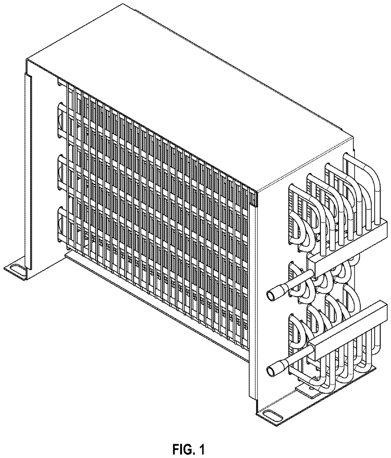
Patent details
| Patent no. | US D785,151 S (US design patent) |
|---|---|
| Title | Condenser |
| Applicant | ATM Beyaz Eşya Parçaları Sanayi ve Ticaret Ltd. Şti., GOSB – Gebze/Kocaeli, Türkiye |
| Inventor | Besim Oktayer, Gebze/Kocaeli |
| Application no. / filed | 29/499,250 · August 13, 2014 |
| Date of patent | April 25, 2017 |
| Term | 14 years (until 2031) |
| Classification | LOC (10) 23-04 · USPC D23/354 |
The full patent and drawings are available on Google Patents.
What does a design patent protect?
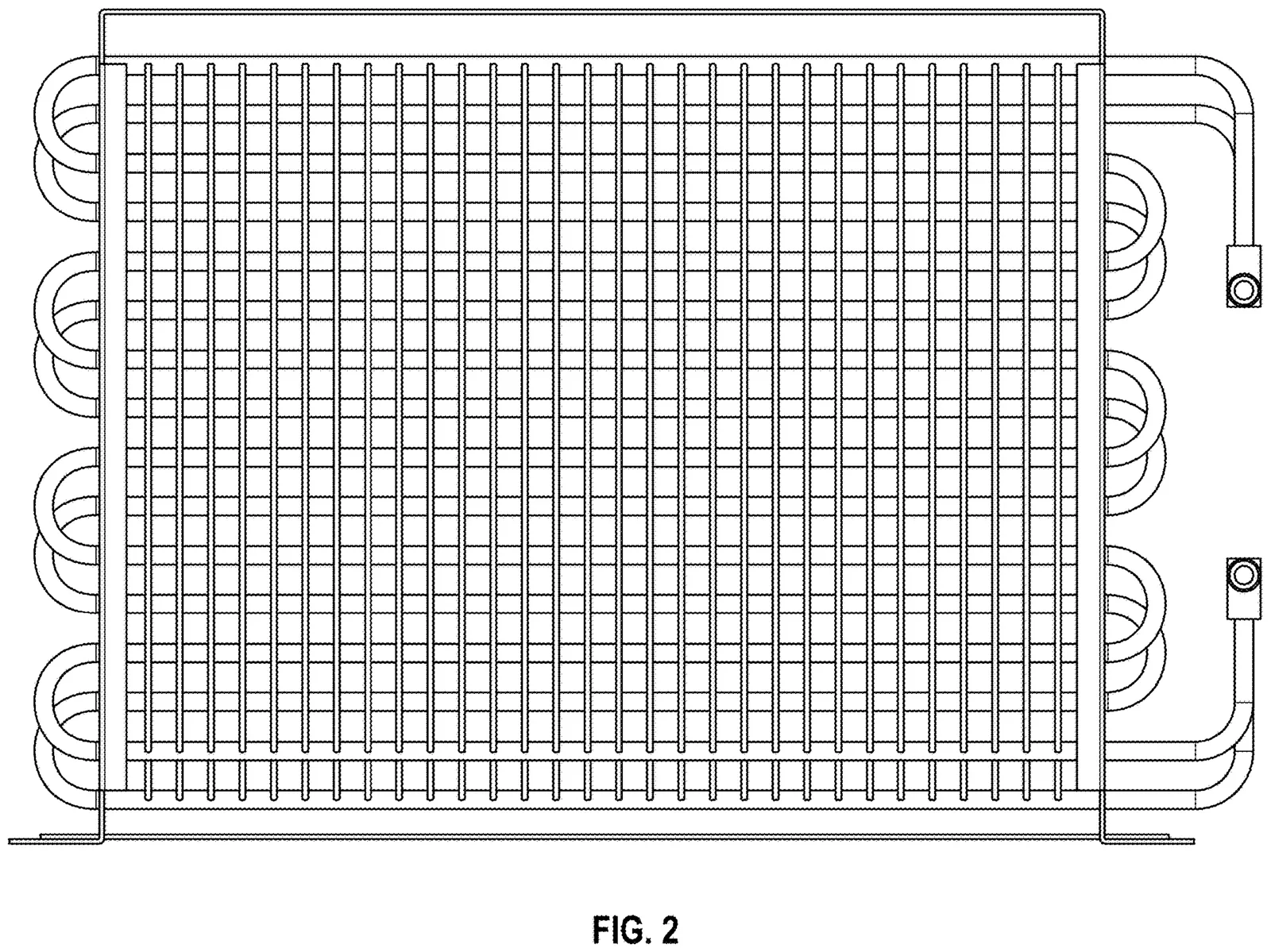
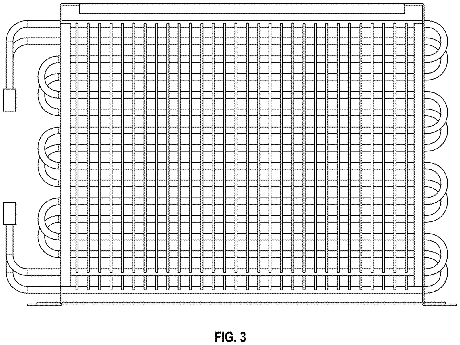
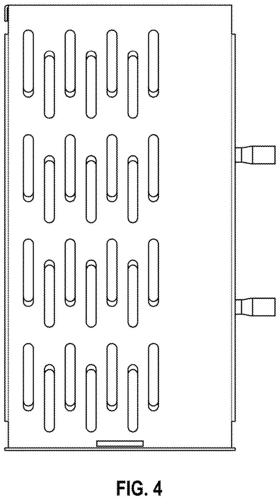
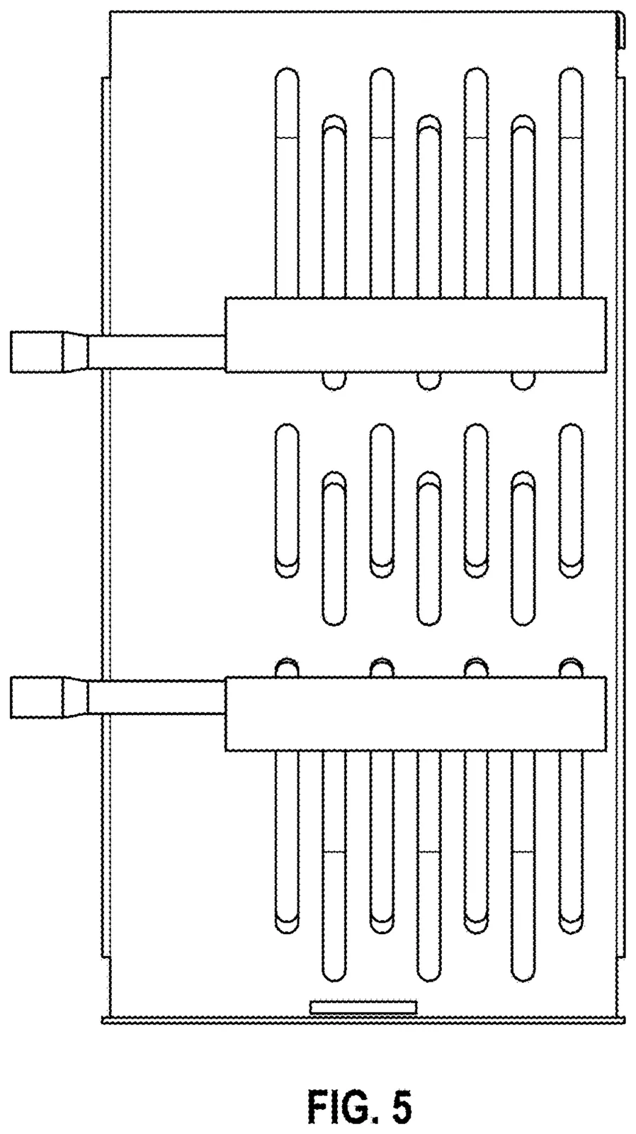
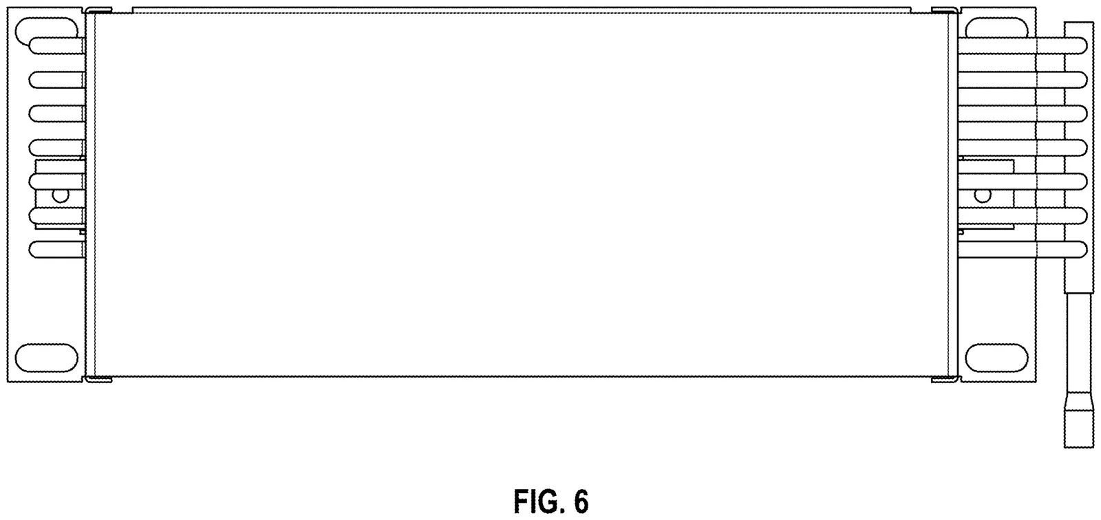
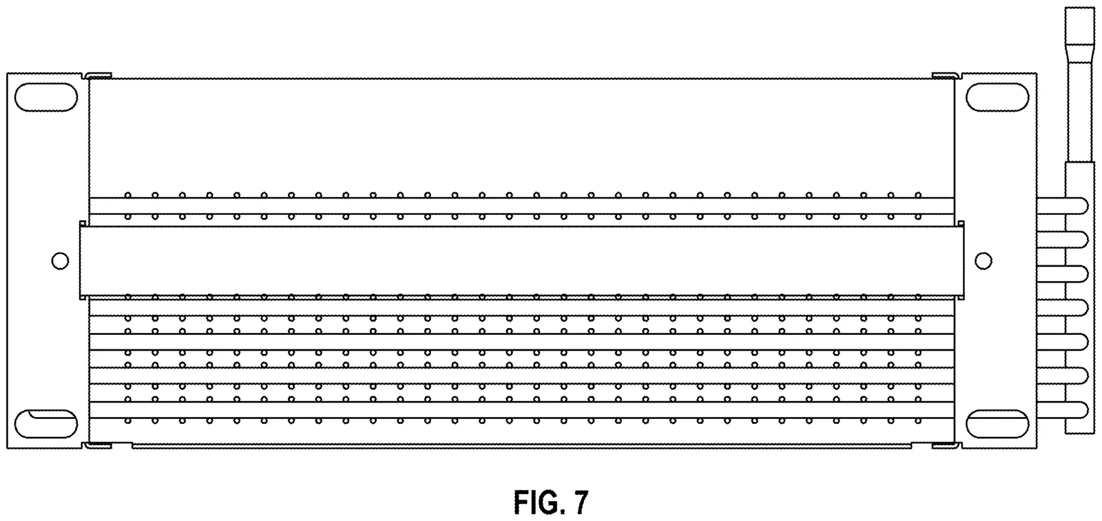
In the US, a design patent protects the appearance of a product: its shape and geometry. The patent's single claim reads: "The ornamental design for a condenser, as shown and described." The drawings, not the text, define the scope of protection, which is why the patent describes the product completely from seven angles.
The ATM Condenser from seven angles
The engineering behind the geometry
The structure in the drawings is deliberate. The tube layout is designed for maximum heat transfer, and the headers group the individual condenser sections in parallel, increasing system efficiency. Because the gaps between the wires don't clog over time the way fins do, the condenser keeps its first-day performance.
- Doesn't clog, needs no filter: no periodic cleaning service required.
- 30–70 % less refrigerant: for the same heat transfer, compared with finned coils.
- Low air-side pressure drop: the fan uses less energy.
- Burst resistance up to 300 bar: safe for high-pressure CO₂ (R744) systems.
- Natural refrigerants: works with CO₂ and the hydrocarbons R290 and R600a.
- UL certified.
Developed for applications with active air circulation: supermarket cabinets, cold beverage display units, upright display cases and commercial coolers running on CO₂ or hydrocarbons.
Part of a patent family
US D785,151 S is one link in our group's long-running R&D work in heat transfer. Most of the ideas you see in the drawings developed step by step through inventions the same team registered earlier:
- Multi-Piece Condenser (2007) (TR200708522U): wire-fitted coils built as several interconnected condenser groups.
- Parallel Connected Dust-Free Condenser (2007) (TR200701653A2): independent coils in parallel between inlet and outlet, for a more compact condenser. The basis of the parallel grouping in the ATM Condenser.
- Plate Condenser (2008) (TR200803279U): a condenser whose tubes are enclosed by a plate.
- Series-Connected Staggered Heat Exchanger (2015, PCT) (WO2016144276A1): fine wires increase the heat transfer surface and staggered coils keep it dust-free and efficient. Published as an international application.
- High Efficiency Wire Condenser (2018) (TR201808619U5): weld-free, one-piece connecting tubes folded staggered at 45°: more heat transfer area with no leak points and no blocked airflow.
The full list is in the Industrial Property Rights section of our R&D page.
At TOYER's Design Center, approved by the Turkish Ministry of Industry and Technology, we work on the production technology that makes products like this possible: condenser production lines, tube forming and welding machines. For full product details, visit the ATM Condensers product page.
Planning a similar product or production line? Get in touch and let's look at it together.